Absolute vs relative stability explained through fracture patterns, real orthopaedic implants, radiographs and everyday clinical decisions.
The clinical question: Not “Which implant is the strongest?” but “What mechanical environment does this fracture need to heal?” Compression, bridging, nailing and external fixation are different tools for achieving that environment.
1. Overview — what is fracture fixation?
Fracture fixation holds broken bone fragments in an alignment that permits healing and function. The chosen method must control length, alignment and rotation while respecting bone vascularity and the surrounding soft-tissue envelope.
| Core goal | Practical meaning |
|---|---|
| Mechanical stability | Control deforming forces and fracture-site movement. |
| Biological preservation | Protect blood supply, periosteal connections, hematoma and soft tissues as appropriate. |
| Restoration of anatomy | Accurately reconstruct joints; restore appropriate shaft length, axis and rotation. |
| Functional recovery | Allow safe rehabilitation according to fixation stability and the injury. |
For bone-healing biology, read Fracture Healing: Stages and Biomechanics before this module.
2. Let fracture morphology guide the fixation strategy
A simple fracture can often be reduced and compressed. A comminuted diaphyseal fracture generally benefits from an approach that preserves intermediate-fragment biology instead of stripping every fragment to reconstruct it anatomically.
| Fracture pattern | Common fixation concept | What matters most |
|---|---|---|
| Simple transverse diaphysis | Compression plate (absolute) or appropriately indicated nail (usually relative) | Contact/compression or controlled intramedullary stability |
| Simple long oblique / spiral | Lag screw fixation ± neutralization plate | Compression across a reducible plane |
| Multifragmentary diaphysis | Bridge plating, locked nail, selected external fixation | Length, axis, rotation and vascular preservation |
| Intra-articular fracture | Anatomical reduction with stable interfragmentary fixation of major joint fragments | Joint congruity; metaphyseal zone may be bridged |
| Open/high-energy injury | Temporary or definitive fixation according to soft tissues and contamination | Resuscitation, debridement, coverage, stability |
 ↗ View larger image
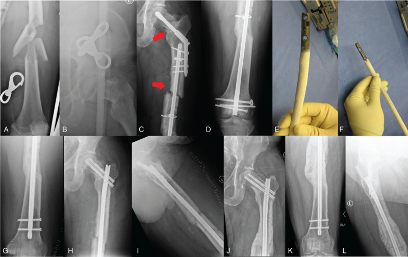
Why a real fracture can demand more than one fixation technique
These clinical radiographs show a complex femoral neck–shaft injury and subsequent fixation/revision. A surgeon may need stable articular/neck reduction plus a different shaft strategy. One bone can contain more than one mechanical problem.
The image illustrates complexity, not a claim that one particular construct is ideal for every such injury.
3. Absolute stability — compression and direct healing
Absolute stability aims to eliminate clinically relevant interfragmentary motion under physiological load. It is commonly achieved by interfragmentary compression with lag screws and/or compression plates. Direct cortical remodeling predominates; abundant external callus is not required.
| Characteristic | Absolute stability |
|---|---|
| Reduction | Anatomical apposition of fracture surfaces or major articular fragments |
| Motion | Minimal interfragmentary movement |
| Biology | Direct cortical/osteonal remodeling |
| Radiograph | Little external callus may be entirely normal |
| Common examples | Simple diaphyseal compression plating; properly compressed articular fragments |
4. Relative stability — biological fixation and callus
Relative stability allows a controlled degree of elastic movement across the fracture. Appropriate movement encourages secondary healing: hematoma → soft callus → hard callus → remodeling. Too much motion, however, may prevent bridging and lead to failure.
| Characteristic | Relative stability |
|---|---|
| Reduction | Functional alignment (length, axis, rotation); avoid unnecessary stripping |
| Motion | Controlled interfragmentary micromotion |
| Biology | Endochondral and intramembranous callus formation |
| Radiograph | Progressive callus and cortical bridging usually expected |
| Common examples | Bridge plate, intramedullary nail, external fixator, cast |
 ↗ View larger image
What happens if motion exceeds the healing environment?
This tibial pseudarthrosis radiograph shows abundant callus without successful bridging. It illustrates why callus formation alone does not prove union. A mechanically inadequate construct can prevent consolidation despite active biology.
Interpret together with symptoms, serial imaging, infection risk and the treatment history.
Clinical application: Delayed Union & Nonunion explains why insufficient mechanical control can stall healing.
5. Lag screws, compression plates and bridge plates
Lag screw — interfragmentary compression
A lag screw compresses two bone fragments when the near fragment can glide and threads obtain purchase in the far fragment. Screw direction is ideally perpendicular to the fracture plane to maximize compression. In very oblique fractures, a neutralization plate can protect the lag construct from bending and torsion.
Dynamic compression plate (DCP)
An eccentrically placed cortical screw in an appropriate dynamic compression hole draws a precontoured plate toward the fracture, creating axial compression. Reduction, contouring and screw sequence are critical; simple fractures may be treated with the compression principle.
| Plate mode | Mechanical role | Expected healing |
|---|---|---|
| Compression | Interfragmentary force at a reducible fracture plane | Usually primary/direct |
| Neutralization | Protects an independently compressed fracture against shear/bending/torsion | Depends on compression and global mechanics |
| Bridge | Spans a multifragmentary zone without compressing each intermediate fragment | Usually secondary/callus |
| Buttress/antiglide | Resists shear and fragment translation at a specified geometry | Depends on fracture reduction and stability |
 ↗ View larger image
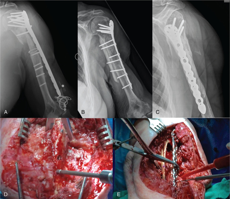
A real plated fracture: interpret the whole construct
This published clinical series shows proximal humeral fixation failure and revision. Plates can serve compression, buttress, neutralization or bridge roles depending on technique. Do not identify stability type from the presence of a plate alone.
Implant breakage or screw migration requires reassessment of union, reduction and mechanics.
For an operative application of distal radius volar plating, see our Smith Fracture Surgical Approach.
Bridge plate — a splint across comminution
A longer plate fixed to the main proximal and distal fragments can preserve the vascular attachments of comminuted intermediate pieces. Reduction prioritizes length, alignment and rotation, rather than reconstructing every shard. Locking screws can help when the plate functions as an internal fixator, but both locking and conventional constructs must be planned for suitable stiffness.
 ↗ View larger image
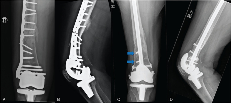
Plate failure is a mechanical warning, not a plate-type diagnosis
This real periprosthetic distal femoral nonunion series shows failed fixation followed by revision. Assess bone stock, fracture gap, implant length, fixation distribution, alignment and prosthesis stability.
These are complication/revision films; not an illustration of routine uncomplicated bridge healing.
6. Intramedullary nailing — load sharing and controlled stability
A locked intramedullary nail lies close to the bone mechanical axis and resists bending while interlocking bolts constrain rotation and length. In most diaphyseal patterns it functions as a relative-stability construct with secondary healing; the exact environment depends on reduction, nail fit, locking configuration, gap and loading.
 ↗ View larger image
What does a locked intramedullary nail look like?
This is an actual proximal femoral nail with cephalocervical and distal locking hardware. Locking elements maintain rotational/axial control; they do not automatically compress all fracture planes.
Key point: implant design, proximal/distal fixation and fracture location matter more than the word “nail”.
 ↗ View larger image
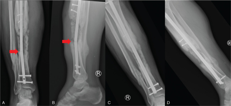
Clinical example — nail failure with nonunion
These radiographs demonstrate tibial nonunion with intramedullary implant failure and revision. Common issues to examine include gap, alignment, nail diameter, locking integrity, infection and union progression.
Exchange nailing, augmentation or another strategy requires fracture-specific planning; implant failure is not treated simply by a stronger rod.
7. External fixation — temporary and definitive stability
External fixators transmit load through percutaneous pins or wires and an external frame. They may be used temporarily in a major soft-tissue injury or definitively in selected fractures, reconstruction or infection settings. Stability depends on frame geometry, pin spread, connecting bars, distance from bone and loading.
 ↗ View larger image
Actual external fixation X-rays
This is a real distal radius external fixator in frontal and lateral radiographs. It demonstrates fixation outside the skin with pins connected by an external frame.
Do not assume an external fixator is always flexible: constructs can range from very stiff to relatively permissive of movement depending on configuration.
8. Interfragmentary strain — the key biomechanics concept
Strain = change in fracture-gap length ÷ original gap length. It explains why a tiny gap with persistent motion can create a hostile environment for hard-bone bridging. The classic teaching thresholds are conceptual ranges; they are not universal bedside surgical cut-offs.
0.2 mm motion ÷ 1 mm gap = 20% strain
Persistent motion relative to a short gap can make mineralized bridging difficult.
0.2 mm motion ÷ 4 mm gap = 5% strain
The same motion across a larger gap yields less calculated strain—but a bigger defect still needs effective healing biology.
Optional deeper biomechanics — plate working length & screw density
Bridge construct stiffness varies with plate material, span, plate–bone offset, screw positions, screw density, fracture gap and loading. Increasing the distance between the nearest screws (working length) can reduce local construct stiffness in some configurations, but too much working length or insufficient fixation can cause excessive movement or fatigue. There is no universal best number of empty holes for every fracture.
9. Practical clinical decision pathway
Anatomical reduction and appropriately stable fragment fixation, often with compression where safe.
Choose stability from fracture pattern, biology and soft tissues.
Consider interfragmentary compression (lag screw or compression plate) where indicated.
Consider biological bridge plating, intramedullary nailing or another appropriate relative-stability construct.
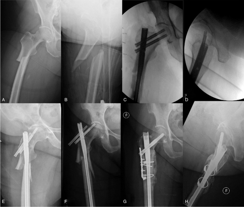 ↗ View larger image
A real-world challenge: fixation failure is multifactorial
This femoral radiographic series illustrates problematic healing requiring revision. Implant strength alone does not determine success: fracture morphology, alignment, strain, patient factors and local vascularity all affect whether the construct lasts until union.
Consider both mechanical and biological failure in any painful delayed union.
10. High-yield revision — one-minute summary
11. Clinical viva — click to reveal answers
Ten short questions, arranged from biomechanics to operative decision-making.
1. What is absolute stability?
2. What is relative stability?
3. Does a locking plate automatically create absolute stability?
4. Why does a simple transverse fracture suit compression plating?
5. Which way should a lag screw be directed?
6. Why avoid exposing comminuted fragments in bridge plating?
7. How can a patient have an intra-articular and comminuted metaphyseal fracture together?
8. What is interfragmentary strain?
9. What does no visible callus after rigid compression plating mean?
10. Why can a bridge plate fail despite being long?
12. Interactive 20-question practice mock
One question at a time. Choose A–D for immediate feedback and option-by-option explanation. Next unlocks after selection; score and answers stay on this browser.
Select an option to reveal explanation and unlock Next.
13. References & Image Credits
Show references and image credits (+)
Medical and surgical sources
- AO Surgery Reference — Basic Principles of Plating
- AO Surgery Reference — Compression plating of simple transverse femoral shaft fracture
- AO Surgery Reference — Multifragmentary tibial fractures: compression vs relative stability
- AO Surgery Reference — Articular reconstruction and bridge plating principles
- Orthobullets — Fracture Healing
- Orthobullets — original educational vignette comparing stability
- Benulič et al. Mechanobiology of indirect fracture healing under relative stability, 2022
- Hoit, Bonyun & Nauth: Hardware considerations in infection/nonunion, OTA Int 2020 (figures licensed CC BY 4.0)
Source image addresses and licences
The clinical figures below are linked under their stated licences. Images are displayed unaltered; webpage layout scales them without changing underlying medical content. Direct-image URLs are provided for checking and replacement if hotlinking fails.
- External fixation of distal radius fracture — AP and lateral X-rays
Ashish j29 / Wikimedia Commons · CC BY 3.0
Direct image URL - Actual proximal femoral intramedullary nail with proximal and distal locking screws
Andreas Franzkowiak (Bullenwächter) / Wikimedia Commons · CC BY 3.0
Direct image URL - Tibial nonunion with failed intramedullary nail and revision radiographs
Hoit, Bonyun & Nauth, OTA International 2020, Fig 6 · CC BY 4.0
Direct image URL - Complex femoral neck–shaft nonunion and revision fixation: sequential radiographs
Hoit, Bonyun & Nauth, OTA International 2020, Fig 2 · CC BY 4.0
Direct image URL - Proximal humeral nonunion with failed hardware and revision fixation
Hoit, Bonyun & Nauth, OTA International 2020, Fig 5 · CC BY 4.0
Direct image URL - Distal femoral periprosthetic plate failure and revision fixation
Hoit, Bonyun & Nauth, OTA International 2020, Fig 7 · CC BY 4.0
Direct image URL - Atypical femoral fracture, fixation failure and revision: imaging sequence
Hoit, Bonyun & Nauth, OTA International 2020, Fig 3 · CC BY 4.0
Direct image URL - Tibial pseudarthrosis with prominent callus (clinical radiograph)
Jmarchn / Wikimedia Commons · CC BY-SA 3.0
Direct image URL
Original educational synthesis. Updated October 2026. Individual fracture treatment requires patient-specific orthopaedic assessment.


0 Comments